Introduction
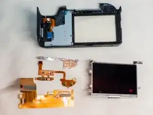
This guide will show you how to disassemble the LCD screen assembly. This can allow you to replace the individual parts on the LCD assembly such as the LCD screen, the LCD screen window, and the FPC assembly.
-
-
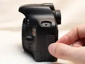
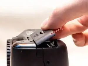
Pry open the rubber I/F terminal cap with your finger.
-
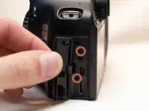
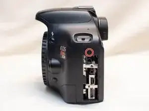
Remove the two M1.7x2.5mm JIS #000 screws that are underneath the I/F terminal cap.
-
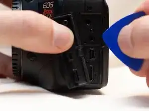
Using a plastic pick, or another thin plastic prying tool, pop off the I/F terminal cover from the camera.
-
-
-
On the left side of the camera, remove the following screw:
-
One M1.7x6.0mm JIS #000 screw
-
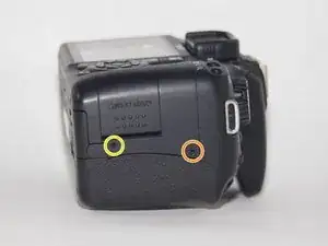
On the right side, remove the following screws:
-
One M1.7x5.5mm JIS #000 screw
-
One M1.7x3.5mm JIS #000 screw
-
-
-
Remove the battery door.
-
Open the battery door to about a 35° angle.
-
Pull the battery door straight outwards.
-
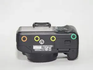
Remove the following screws from the bottom of the camera:
-
One M1.7x6.0mm JIS #000 screw
-
Two M1.7x2.5mm JIS #000 screws
-
One M1.7x5.5mm JIS #000 screw
-
-
-
Slide the viewfinder eyepiece vertically upwards.
-
Start to pull the back cover partially off of the camera.
-
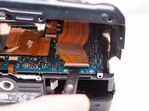
Disconnect the LCD screen ribbon cable from the main PCB board.
-
Use a plastic spudger to lift up the black locking tab.
-
Carefully pull out the ribbon cable from its connector using a pair of angled tweezers.
-
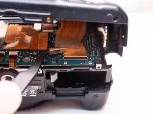
Finish pulling the back cover off of the camera body.
-
-
-
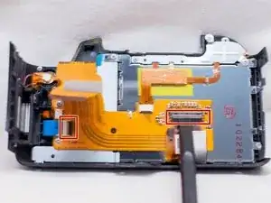
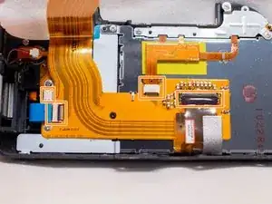
Use a plastic spudger to lift up the locking tabs on the two ribbon cable connectors.
-
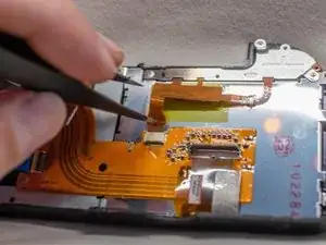
Remove the four ribbon cables connected to the FPC assembly.
-
Stick one of the ends of a pair of pointed tweezers through the hole in the ribbon cable and carefully pull the ribbon cable out of each connector.
-
-
-
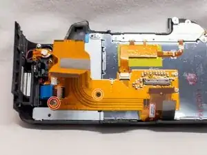
Remove the following screws from the back cover FPC assembly:
-
One M1.7x3.5mm JIS #000 screw
-
One M1.7x4.0mm JIS #000 screw
-
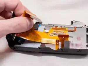
Carefully slide out the back cover FPC assembly from underneath the metal tabs holding it in place.
-
-
-
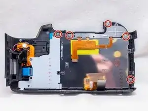
Remove the following screws on the LCD screen assembly:
-
Five M1.7x3.5mm JIS #000 screws
-
Pull off the metal holding plate.
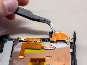
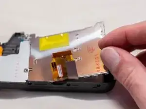
-
With a pair of angled tweezers, carefully pull off the DOS FPC assembly.
-

To reassemble your device, follow these instructions in reverse order.