Introduction
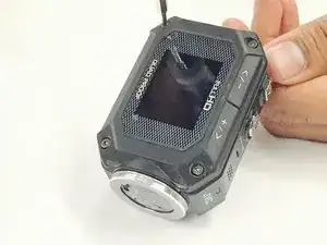
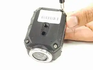
If the power or record button isn't working on your JVC Adixxion GC-XA1BU, follow the instructions to replace the board. To complete this guide, you will need to purchase a new power/record button board and make sure that you have the tools listed. It is always good practice to make sure that the device is completely powered off and remove the battery before attempting any repairs.
-
-
Remove the 8 screws (5mm x 4mm) from the corners of both the front and back of the camera (4 screws on each side) using the T6 Torx screwdriver.
-
-
-
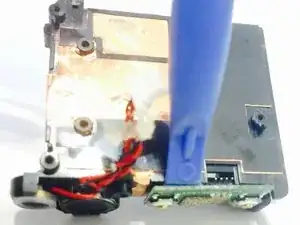
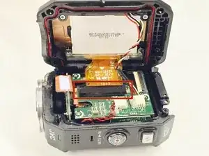
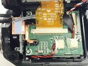
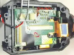
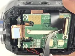
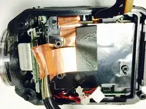
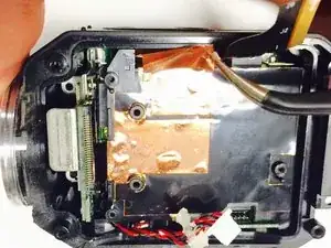
Carefully peel off the glue holding the red and black braided wire down to the circuit board. Then remove the connector by gently pulling it out of its casing. You will want to save this glue as it may come in handy when re-assembling your device.
-
-
-
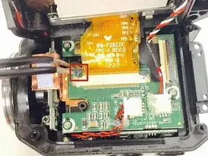
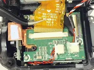
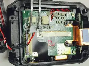
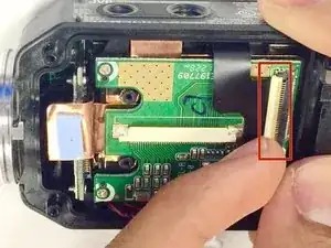
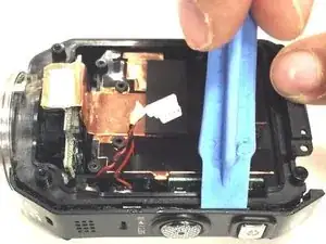
Lift up the white ribbon clip and remove the black ribbon by gently pulling it away from the white clip.
-
-
-
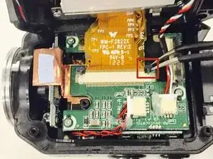
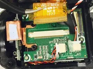
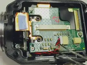
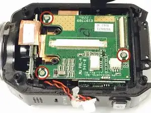
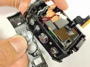
Remove the the three Phillips screws (3mm headsize x 2mm length) from the circuit board. After you remove the screws, you can then remove the green circuit board by lifting it up out of the device case. You may want to use the plastic opening tool to get start lifting the circuit board.
-
-
-
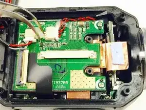
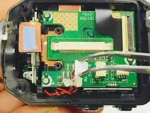
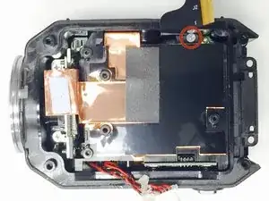
Once the circuit board is removed, you will want to remove the Phillips screw (3mm headsize x 2 mm length) near the ribbon cable. ONLY REMOVE THIS ONE SCREW.
-
-
-
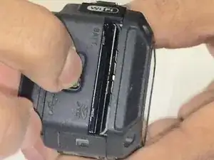
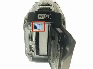
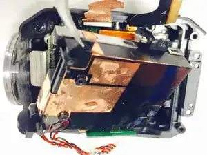
Use the plastic opening tool to gently remove the top cover from the camera. It is glued on, so you may need to work at it to get it to come off.
-
-
-
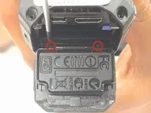
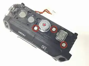
Once the cover has been removed, you will want to remove the three Phillips screws (2mm headsize x 2mm length) that are underneath.
-
-
-
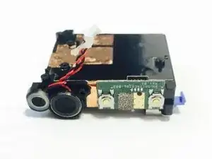
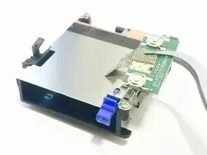
Now you should be able to gently remove the battery housing out of the device. If you are having difficulty getting the battery housing to come out, you may want to use the plastic opening tool to help get it started.
-
-
-
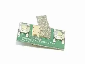
The power and record buttons are glued to the battery housing, so use the plastic opening tool to gently pry off and remove the buttons.
-

To reassemble your device, follow these instructions in reverse order.