Introduction

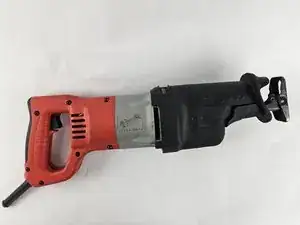
This simple guide shows how to remove and replace the blade clamp and the torsion spring on your Milwaukee Sawzall 6520-21 if it does not function properly.

  1. CqKGEbvGifkJQZKp
    CqKGEbvGifkJQZKp
    JnmIMKZdtoCESK2j
    aRGai4lo3WvdkPxE
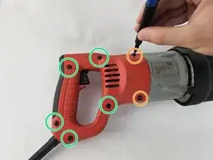
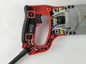
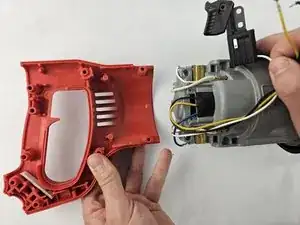
    • Unplug the Sawzall and Orient the right half-handle to face upwards.

    • With a T20 Torx screwdriver, remove the following screws:

    • 7-18 x 1.125-inch Slt. Plastite T-20

    • 8-16 x .625-inch Slt. Plastite T-20

    • The right-half handle does not contain any wires on the underside.

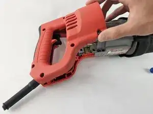
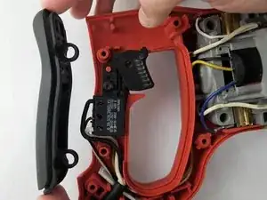
    • Lift the handle off.

  2. 2dZyLZkULuCtThK5
    2dZyLZkULuCtThK5
    Pt42oEaToQl1j5bt
    • Two rubber rings around the divots hold the cushion grip to the handle.

    • Lift off the cushion grip.

  3. BffUlEGiRNHTXH2g
    BffUlEGiRNHTXH2g
    LUAhWoIrpuBvwHG3
    • Remove the screw above the trigger.

    • 8-16 x .625-inch

    • The trigger wires threaded through the handle are not fastened. They do not require any tool to pull out.

  4. FRpY1YJQCxAEqR2Y
    FRpY1YJQCxAEqR2Y
    mHT4JNjMvEcGaVYG
    JKWixYAaiRIKpq2A
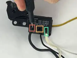
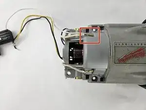
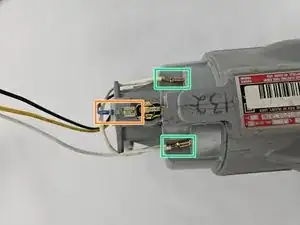
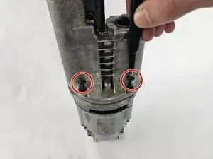
    • Take a 1.5mm flathead screwdriver and insert it into the pin lock above each of the wires:

    • Black wire: Insert it on the left side of the pin. Pull the wire while gently rotating it clockwise

    • Black wire: Insert it on the bottom side of the pin and gently rotate it counterclockwise

    • White wire: Insert it on the right of the pin and gently rotate it counterclockwise

  5. cWSOI2iuKwAxDYBW
    cWSOI2iuKwAxDYBW
    NRZfPIdrHxJcqVfL
    • Gently pull the yellow electrical wire.

  6. AYpBNaWTSTfUkYsT
    AYpBNaWTSTfUkYsT
    rlYZQnXLJ4YRUaPs
    m5TvbGukqRLVqQbV
    • The left half handle and motor housing can separate without difficulty.

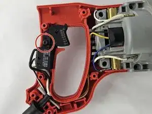
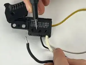
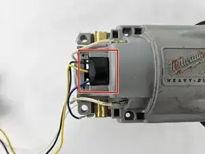
    • The trigger paired with the motor housing wire requires two removals.

    • Gently remove both white wires.

  7. HmORB2MEWFiCFRWY
    HmORB2MEWFiCFRWY
    5iGSafPMm13tGxtG
    r1aNEZLF5tuxtoBR
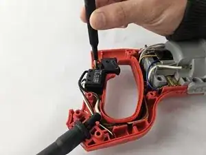
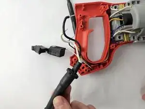
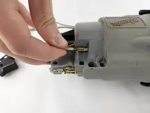
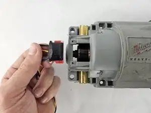
    • Gently slide the following from the motor housing:

    • Black chip.

    • Blue electrical wire.

    • Two, white electrical wires.

  8. VvDyWT2RRHGkfgAu
    VvDyWT2RRHGkfgAu
    MKOeQhtxRKsLeKyM
    fsPBSTLdmJhARmWR
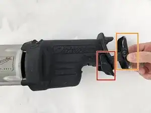
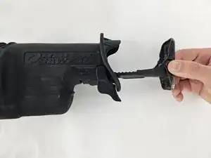
    • Set the shoe release lever in its unlocked position.

    • Remove the shoe assembly.

    • There is a pin that holds the shoe release lever

    • Detach the lever.

  9. quPWquNhgvyfM4Pd
    quPWquNhgvyfM4Pd
    hL5OCLJQ2lDhIlsA
    2tACc1uitHYIC5A6
    • Push or pull the shoe pin to remove it from the gear case insulator.

    • Remove the insulator.

    • This requires a lot of force to remove. It's recommended to have help from another person.

  10. mTV1ACPYGmMVRywU
    mTV1ACPYGmMVRywU
    WG4LswpoHSlDcQNx
    6A2kASdVEFWYEYNB
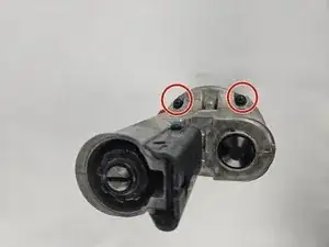
    • Use a T20 Torx screwdriver to remove the following four screws from the gearcase:

    • K50 x 60 mm Washer Hd. PT Screw

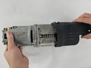
    • Detach the motor housing from the gearcase.

  11. wICUBEsU5eo3LebG
    • Position the transmission housing upright so the blade clamp assembly faces upwards.

  12. nspVHTZ16ZChA2We
    nspVHTZ16ZChA2We
    x3yBDMLLDTOsYZ23
    gXLWxqMdvjtd2DXE
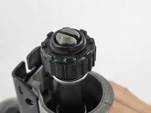
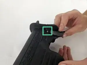
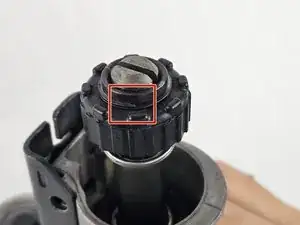
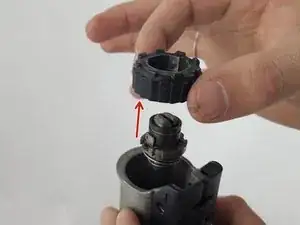
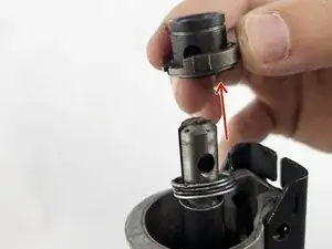
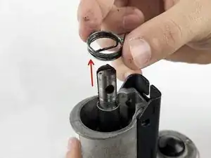
    • Using a flathead screwdriver, insert the head of the driver vertically and twist clockwise to pry the retaining snap ring open and off the blade clamp assembly.

    • Slide the blade clamp upwards.

  13. JgfoXbCp16d2PSkg
    JgfoXbCp16d2PSkg
    1YLSqNnja42gKtoj
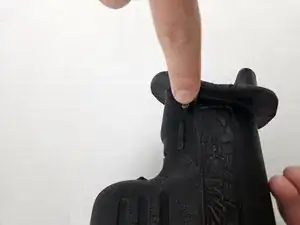
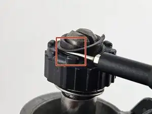
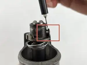
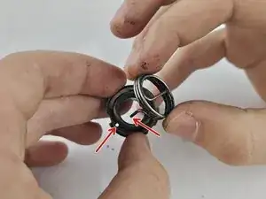
    • To replace the torsion spring, use the flathead to pry the retaining pin beneath its square head.

    • Pull the retaining pin out.

  14. jVei2NsrxmWmii2a
    jVei2NsrxmWmii2a
    PMSnK1TmOkXDtxpK
    ZbvtffMOQlbpTqDJ
    • Pull and slide the assembly and torsion spring off of the spindle.

  15. YjvAvmuREZEv2SDG
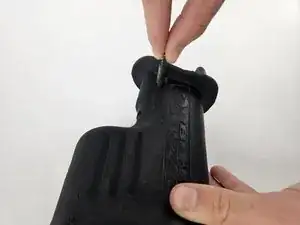
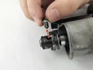
    • When replacing the torsion spring, insert the pin into its respective hole within the assembly.

Conclusion

To reassemble your device, follow these instructions in reverse order.

sebastien_blondeau

Member since: 23/10/24

121 Reputation

0 comments